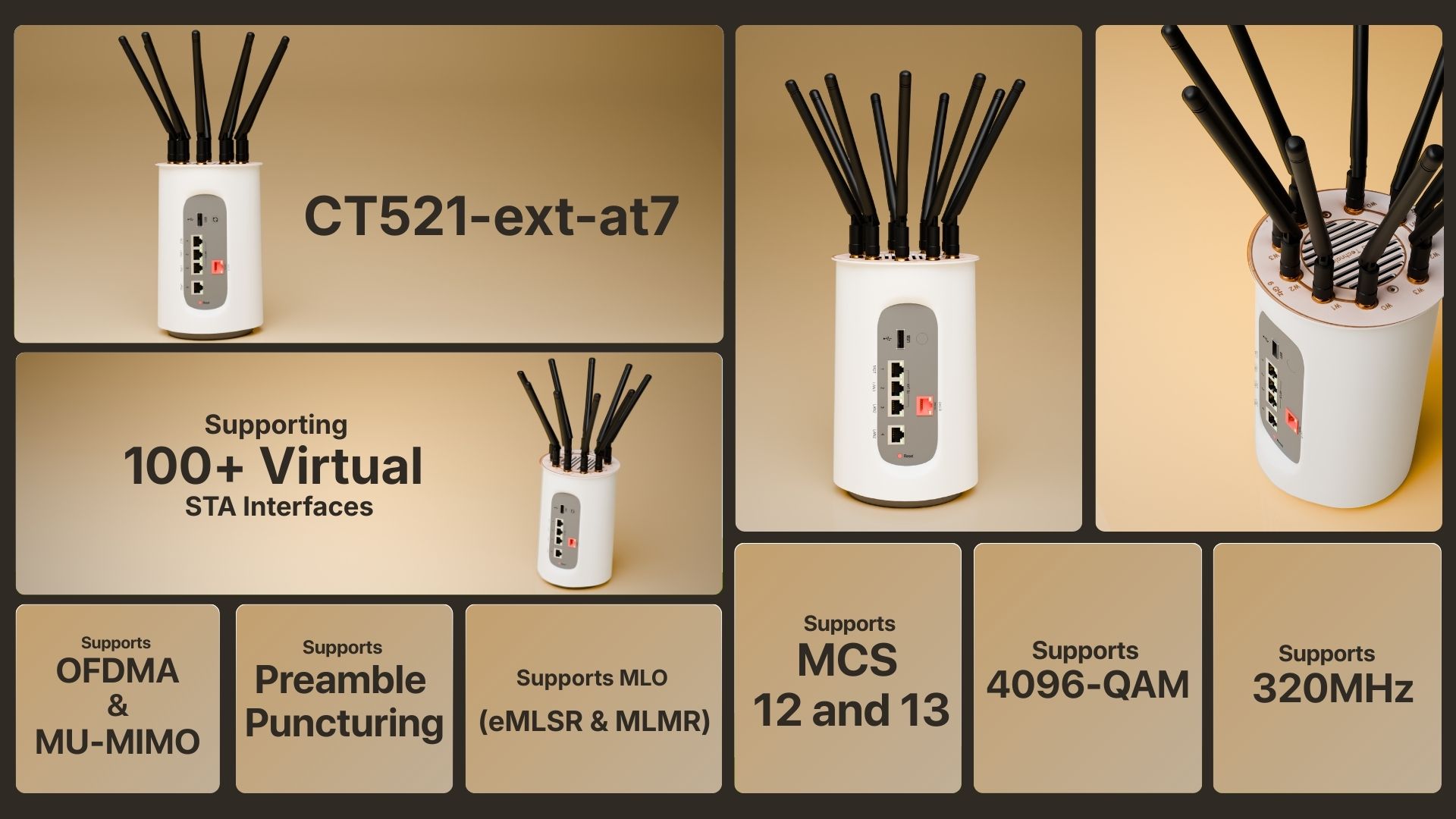
Economy LANforge WiFIRE Wi-Fi 7 1-Radio Traffic Generator Supporting 102 Virtual STA Interfaces
Tri-Band Tri-Concurrent WiFi-7 4x4 Traffic Generator.

Example Network Diagram
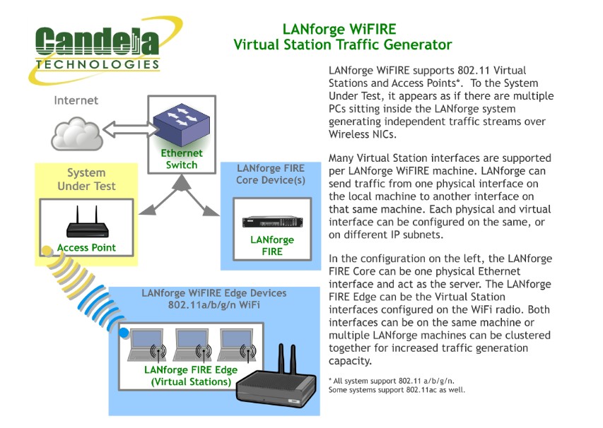
How it Works
LANforge WiFIRE supports 802.11 Virtual Stations and Access Points. To the System Under Test, it appears as if there are multiple PCs sitting inside the LANforge system generating independent traffic streams over Wireless NICs. LANforge can send traffic from one physical interface on the local machine to another interface on that same machine — or out to a real AP and back — at full line rate, with per-station IP, MAC and routing-table isolation.
/// Software Features
Real-World Protocols
- •Layer 2: Raw-Ethernet, 802.1Q VLANs, PPPoE integrated support.
- •Layer 3: IPv4, IPv6, UDP/IP, IGMP Multicast UDP, TCP/IP.
- •Layer 4-7: FTP, HTTP, HTTPS, TFTP, SFTP, SCP.
- •WiFi-7 Wireless Station (up to 102 per machine).
- •Layer 4-7: TELNET, PING, DNS, SMTP, NMAP (via add-on script).
- •File-IO: NFSv3, NFSv4, CIFS, iSCSI.
Performance & Compliance
- •Supports up to 1000 concurrent TCP connections with base license.
- •Able to download about 1.8Gbps WiFi throughput (CPU limited).
- •Supports ToS (QoS) settings for TCP/IP and UDP/IP connections.
- •Comprehensive traffic reports: Packet Transmit/Receive Rate, Drop %, Latency, Jitter.
- •Allows packet sniffing and network protocol decoding with integrated Wireshark.
/// Hardware Specifications
- Affordable Appliance with silent fan.
- Operating System: Debian Linux with customized 64-bit Linux kernel.
- Two 10Gbps, three 1Gbps Ethernet ports.
- Integrated tri-band tri-concurrent MTK7996 4x4 WiFi-7 Radios.
- ARM quad-core 1.9Ghz processor.
- USB Serial console (115200 8 N 1) for console management.
- Dimensions: 8 x 5 x 5 inches (200 x 130 x 130 mm). Weight: 2 lbs.
- Operating Temperature: -20 ~ 45°C.
At a Glance
LANforge GUI Interface
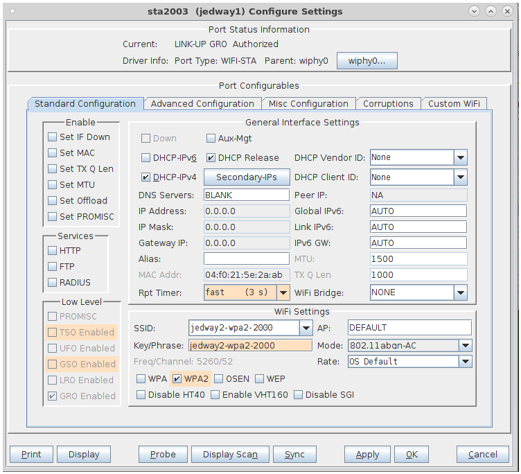
Virtual Station Configuration Screen
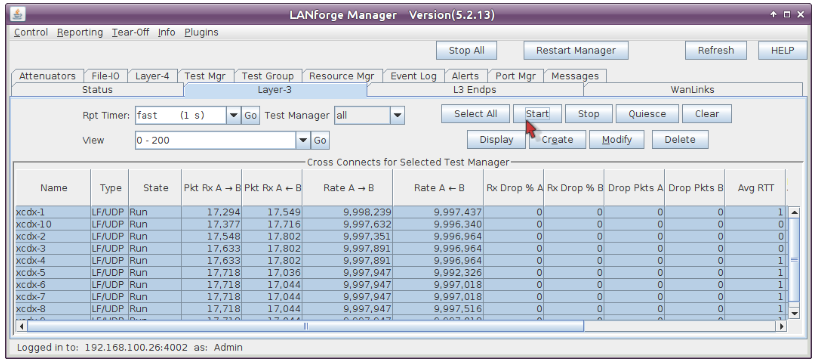
Layer 3 (Ethernet, UDP, TCP) Connections
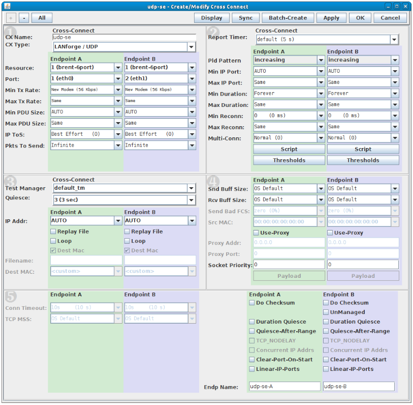
Layer 3 Create / Modify Screen
Quick Start Guide
Step 1
Connect Management Ethernet port to Management network or PC.
Step 2
Connect eth1 wired Ethernet interface to the AP or network under test.
Step 3
Connect power to standard US or European AC power source.
Step 4
The CT521-at7-ext should now boot. If DHCP is available, it acquires an IP; otherwise 192.168.1.101.
Step 5
Install the LANforge-GUI on a separate management PC.
Step 6
Start the LANforge-GUI and click 'Discover'.