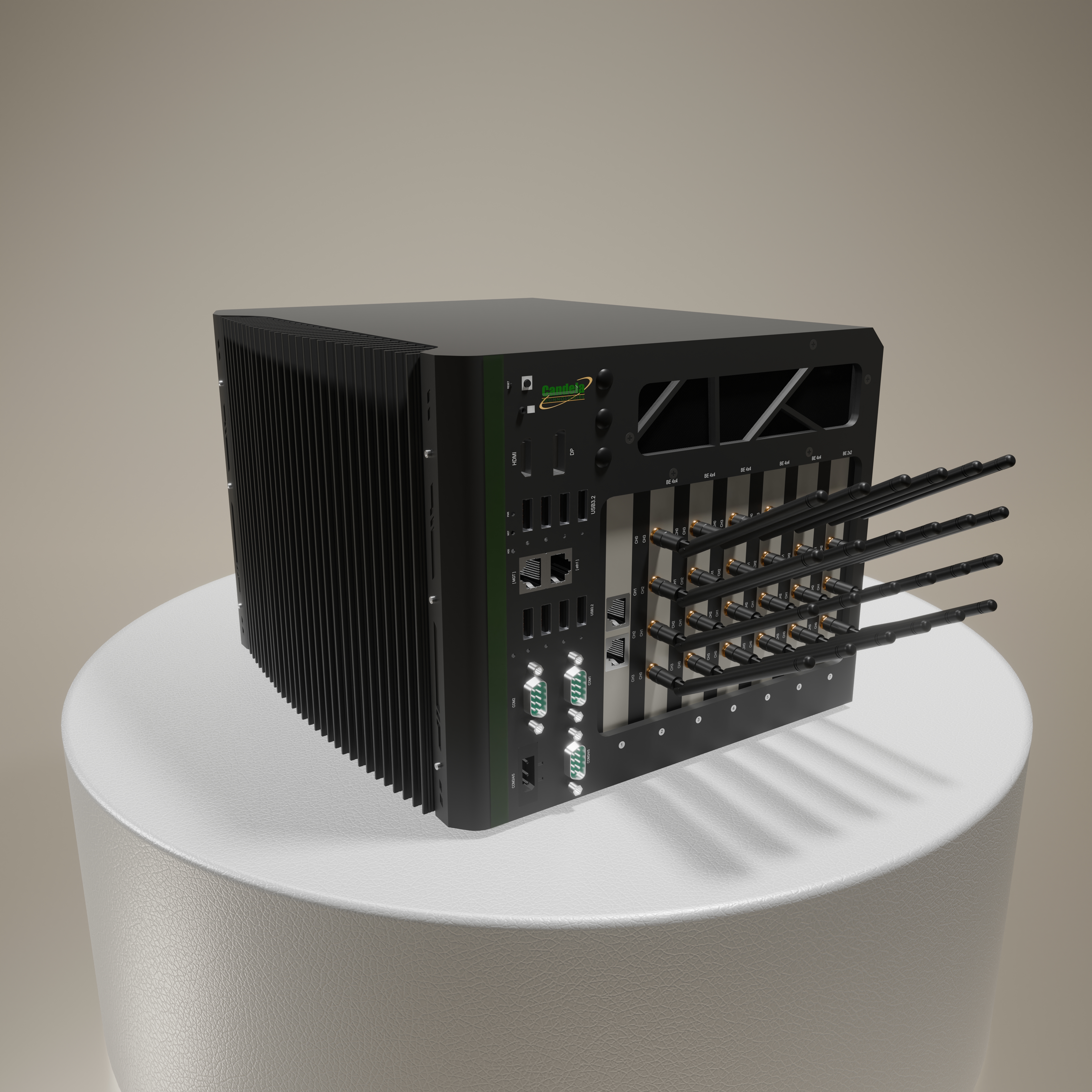
Flagship 7-Slot LANforge WiFIRE Chassis — 500+ Wi-Fi 7 Stations in a Single System
Extreme-Scale Wi-Fi 7 Emulation (500+ Stations).
Example Network Diagram
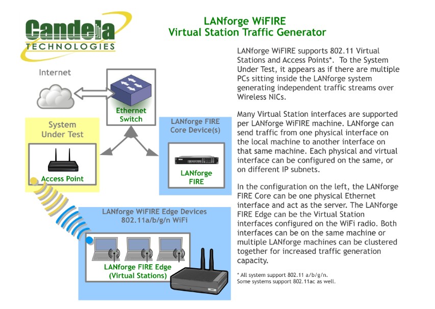
How it Works
LANforge WiFIRE supports 802.11 Virtual Stations and Access Points. To the System Under Test, it appears as if there are multiple PCs sitting inside the LANforge system generating independent traffic streams over Wireless NICs. LANforge can send traffic from one physical interface on the local machine to another interface on that same machine — or out to a real AP and back — at full line rate, with per-station IP, MAC and routing-table isolation.
/// Software Features
Real-World Protocols
- •Layer 2: Raw-Ethernet, 802.1Q VLANs, PPPoE integrated support.
- •Layer 3: IPv4, IPv6, UDP/IP, IGMP Multicast UDP, TCP/IP.
- •Layer 4-7: FTP, HTTP, HTTPS, TFTP, SFTP, SCP.
- •Layer 4-7: TELNET, PING, DNS, SMTP, NMAP (via add-on script).
- •File-IO: NFSv3, NFSv4, CIFS, iSCSI.
- •Per-radio Virtual Stations with independent IP / MAC / routing tables.
Performance & Compliance
- •Up to 1000 concurrent TCP connections with the base license.
- •ToS / QoS settings honoured for both TCP/IP and UDP/IP connections.
- •Comprehensive traffic reports: TX/RX rate, drop %, latency, jitter, RSSI.
- •Integrated Wireshark capture / decode for protocol-level diagnostics.
- •TR-398 Issue 4, RFC 2544 and Wi-Fi Alliance test-plan ready.
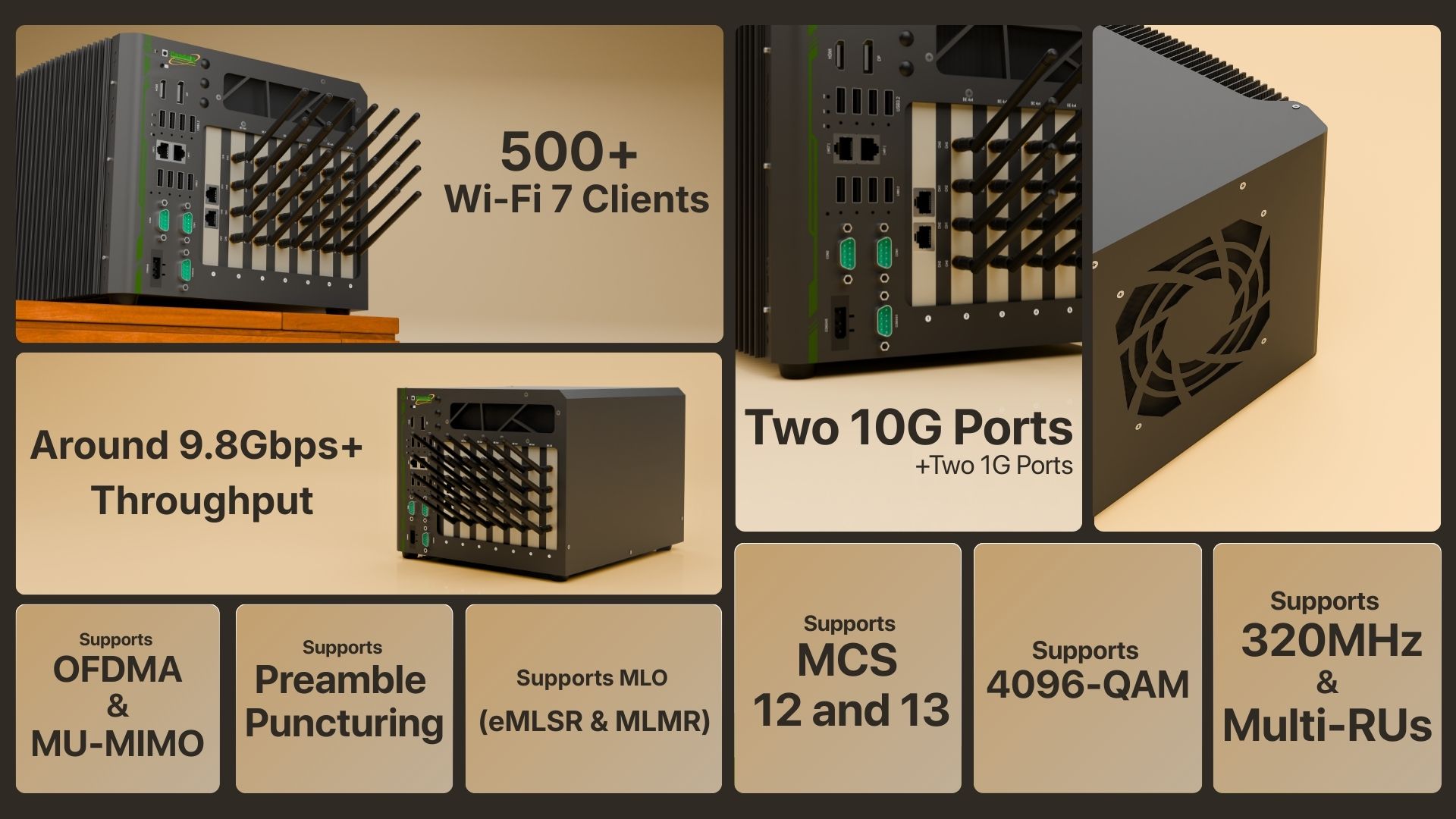
- •Multi-link operation (MLO), OFDMA, MU-MIMO and roaming on supported radios.
Automation & Integration
- •Python scripting and JSON API for full LANforge automation.
- •Chamber View orchestration: AP-Auto, Dataplane, Capacity, Hunt, Rate-vs-Range tests.
- •REST API for CI/CD integration and remote orchestration.
- •Scripted attenuator, turntable and chamber control built-in.
/// Hardware Specifications
- Nuvo 7-slot chassis tuned for radio density.
- Up to 6× MTK7996 4×4 tri-band tri-concurrent Wi-Fi 7 radios.
- Internal splitter / combiner option — choose 4 SMA per radio, or skip the splitter to bring out 8.
- Dual-port 1 / 2.5 / 5 / 10 GbE copper RJ45 NIC for the test uplink.
- Designed for clustering — multiple CT527 chassis combine cleanly for carrier-class tests.
- Each Virtual Station has its own IP, MAC, IP-port space and routing table.
- Debian Linux + LANforge custom kernel.
At a Glance
LANforge GUI Interface
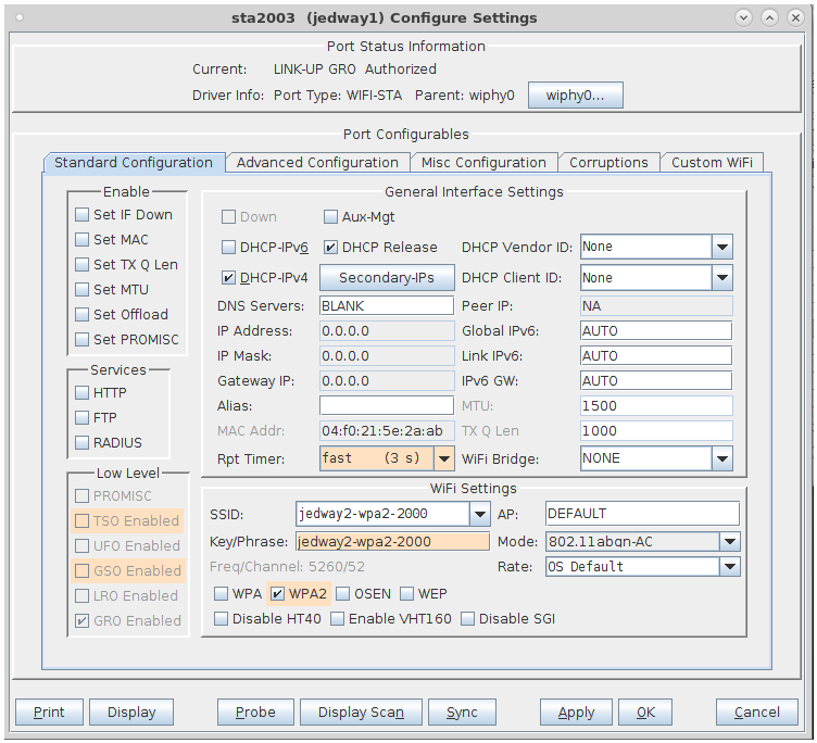
Virtual Station Configuration Screen
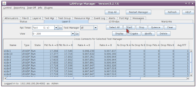
Layer 3 (Ethernet, UDP, TCP) Connections
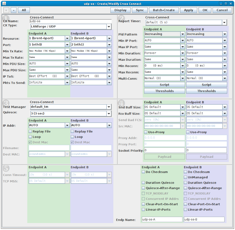
Layer 3 Create / Modify Screen
Quick Start Guide
Step 1
Connect the management Ethernet port to your management network or laptop.
Step 2
Connect the wired test-port (eth1 / 10G uplink) to the AP or network under test.
Step 3
Connect AC power. The system boots into Debian Linux and the LANforge server.
Step 4
If DHCP is available the system acquires an IP automatically; otherwise it falls back to 192.168.1.101.
Step 5
Install the LANforge-GUI on a separate management PC and click 'Discover'.
Step 6
Select the LANforge system, log in, and start creating Virtual Stations.